Developments in welding
Article written by Mark Atkinson and Simon Slater of MACAW Engineering UK; and David Teasdale and James Gilliver of National Grid, UK.
Historically, the shielded metal arc welding (SMAW) process has been used for welding of full encirclement split tees when making “live” hot-tap connections on pressurised gas transmission pipelines.
The National Grid high pressure gas transmission network currently consists of pipelines up to and including 1219 mm outside diameter and up to L555 (X80) grade steel pipe. Due to the size of the split tee assembly that is required for large diameter high pressure pipelines, which can be up to 80 mm thick, the time to manually weld these fittings to the pipeline can be considerable and requires multiple welders to complete welding in one continuous operation.
The qualification of the semi mechanised gas shielded flux cored arc welding (GSFCAW) process for welding the longitudinal seams on large diameter tee connections would realise significant operational and cost benefits over the SMAW method currently adopted, especially for tee thicknesses of 50 mm and above. The equipment for mechanised or semi-mechanised welding is readily available for a large number of applications across many industries. Recent advances in the technology suggest that suitable procedures based on this process could be developed for the longitudinal weld seams of split tee assemblies.
There are several benefits of using a semi-mechanised welding process over manual SMAW, which include:
- High deposition rates.
- Improved slag removal characteristics.
- Higher quality bead appearance and weld profile compared to manual welds.
- Greater control of welding speed and the delivery of more consistent head input.
- A reduction in stop/starts, which lowers the risk of defects associated with these regions.
- A reduction in the number of welders required.
- Prevention of welder fatigue effects through reduced arc time.
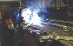
The primary aims of this project were to qualify a semi-mechanised GSFCAW process and procedures for this application and to additionally qualify repair procedures using manual manipulation of the GSFCAW process. These procedures could then be incorporated into the National Grid specification for welding onto pressurised pipelines. A comprehensive welding and test programme was performed using 50 mm BS EN 10028-3 Grade 460 NL2 material selected with a carbon equivalent value, which at 0.49% was towards the upper end of the permitted range. Welding was performed using an orbital welding system adapted for welding in the longitudinal configuration in three positions, PA/1G (downhand), PE/4G (overhead) and PC/2G (horizontal vertical) to cover the full range of welding positions associated with either horizontal or vertical branch off-take connections. An example of test plate welding is shown in Figure 1.
Equipment
The welding system used was the Firefly system supplied by IPWL Ltd, which used the proven Lincoln Electric S350 power wave technology and a game console type welder control unit that provides both a familiar and ergonomic interface to the user. The use of existing off the shelf consumables, filler metal and shielding gas also ensured that once the concept had been developed there would be little additional development required for these and the system could be utilised by the end user if required.
In parallel to the welding development work, the incorporation of specific induction heating equipment was also assessed. This was based on the Miller Proheat 35 equipment and allowed the minimum preheat to be maintained during all welding operations. The integrated thermocouple arrangement delivered additional heat only when required in specific regions of the test plates as well as providing a means of logging interpass temperatures for weld qualification purposes. In addition to the high level of control over welding parameters and resultant heat input, this allowed the overall thermal cycle of the welds to be managed to deliver consistent mechanical properties.
Equipment operation manuals and procedures for both the welding and induction heating equipment along with associated risk assessments allowed the necessary reviews to be carried out, ensuring that all safety aspects were addressed. As with all development work for an end user such as National Grid, the safety implications of such projects are of paramount importance and any operational or policy changes required must be highlighted where deemed appropriate.
All welding was monitored by qualified personnel using ALX weld process logging equipment from The Validation Centre, although the Lincoln Electric system comes with the ability to also log welding parameters for production control and quality assurance.
Welding
During welding, the specific requirements of the governing specifications were satisfied by ensuring procedural controls were acknowledged and implemented. This included actions such as welding initial passes from the centre of the test plate to the outer edges in order to balance distortion. The requirement to ensure start stop regions of each weld were staggered along the length of the weld do not apply as the continuous electrode characteristics of the GSFCAW process allow each weld pass to be deposited for the entire length of the seam, and such regions are therefore naturally contained on the run on and run off plates (other than for the initial passes as mentioned above).
Welding was carried out with only a few minor issues encountered, attributable to fit up limitations of the system related to an excessive root gap as well as some observations on the gas shielding performance on one of the test plates. No issues were encountered that cannot be overcome by following good general practice in setting up and subsequent housekeeping and equipment planned maintenance.
Slag grinding is still required but the slag layer from the flux cored consumable is comparatively fine and exhibits self-detaching characteristics when used with suitable parameters and joint configurations. Some post weld brushing and grinding is still required to achieve optimum weld quality but this is significantly less than typically seen for SMAW welding.
Mechanical testing and NDT
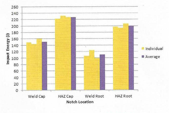
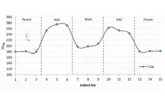
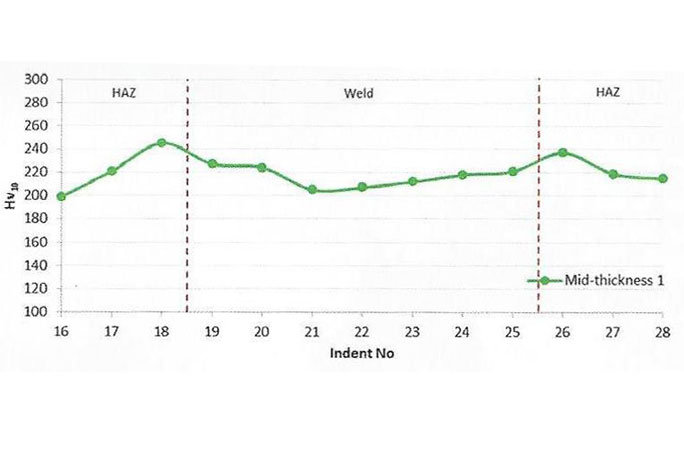
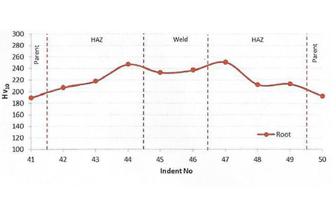
A full suite of mechanical test schedules were drafted and issued for each test weld. These were orientated around both satisfying the qualification requirements of the specification as well as testing additional areas and regions of specific welds for complete characterisation, The positional considerations of the plates and resultant nominal heat inputs were also considered during test specimen extraction to fully account for how these may potentially influence mechanical properties. This was to ensure that the test welds were able to stand as full weld procedure qualification records (WPQR), as well as being able to characterise specific regions of the weld of general interest, and to assist in proving the concept of the system and highlight any concerns or operational limitations when used with typical split tee sleeve materials. Example mechanical test results from the PA position WPQR are presented in Figure 2 to Figure 5.
Once completed welds has been assessed using the magnetic particle inspection and manual phased array stage NDT techniques and progressed to the mechanical test stage, the test extraction was monitored closely to both optimise test coupon material for mechanical test specimen extraction as well as ensuring selected regions assigned for specific characterisation were captured.
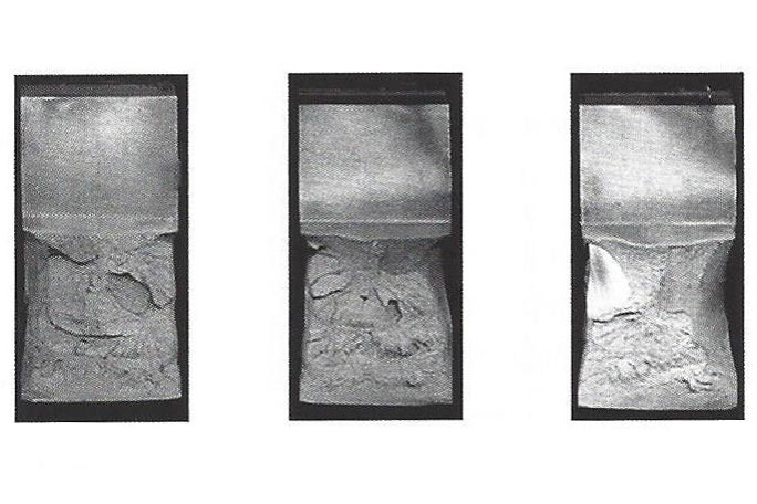
From a mechanical testing perspective all welds (both main seam welds and repairs) produced exceptional results in all positions. Weld metal strength was adequately overmatched to the base material achieving excellent yield and tensile strength values. Weld and heat affected zone (HAZ) toughness was characterised using both Charpy V-notch and crack tip opening displacement (CTOD) methods. Charpy testing carried out at -10°C utilising full size specimens achieved values of over 100 J in the weld and 180 J in HAZ of semi-mechanised welds and over 130 J in both the weld metal and HAZ of repair welds. CTOD testing using B x 2B specimens at -10ºC test temperatures delivered values of 0.78 -1.07 mm for weld metal and 1.26 – 1.33 mm for HAZ. Examples of CTOD fracture faces are shown in figure 6. The excellent toughness values in the HAZ indicate that the heat inputs were low enough to avoid deleterious grain coarsening in this region. The risk with such an approach when using high CEV material can be the consequences of high hardenability, but maximum HAZ hardness values of 287 Hv10 for the main seam welds and 285 Hv10 for the repair welds HAZ are within specification limits. Reported weld metal hardness values of 237 Hv10 and 219 Hv10 for the main seam welds and repair welds respectively means there is no concern of high weld metal hardness being encountered. This is deemed to be a consequence of several factors associated with the set-up including the close control of the pre-heat and interpass using induction heating equipment and its configuration, along with consistent heat input delivery and accurate individual weld bead placement.
Conclusions
The initial review of the GSFCAW process and particular set-up delivered promising results, which demonstrate it is suitable for this application. WPS documents have been developed from the qualification tests that meet the requirements of the National Grid specifications covering welding onto pressurised pipelines. It allows the delivery of consistent and controlled heat inputs across all the welding positions required ensuring control over mechanical properties and weld quality.
The benefits to welders undertaking this type of work are also significant. Less total welding time means less exposure to fume and arc radiation as well as the physical elements of welding onsite, which by the vey nature of the application often takes place in trenches and means workspaces can be cramped and confined. Repeated operations such as electrode changing have been removed and the reduction in required grinding activities has clear health and safety benefits.
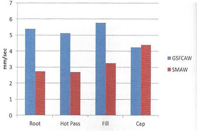
The travel speeds achieved using the GSFCAW process can be up twice those recoded on similar sized fittings welded using SMAW, as shown in Figure 7. As a best estimate across the various positions, an arc time saving of approximately 20% was realised during the work. When these gains are combined with the reduction in ancillary operations, such as changing electrodes and slag removal, the overall productivity gains of the system are clear. Procedures developed during the project support its implementation for this type of welding and further development in assessing the capability of the system to be utilised for circumferential fillet welds is now being considered.
Download PDF of article here.